Table of Contents
1.Article Summary
Electronically Commutated (EC) fans have become the go-to choice in modern HVAC, data center cooling, and industrial ventilation systems. Unlike traditional AC fans that run at a fixed speed, EC fans combine brushless DC motor technology with integrated control electronics, allowing precise, stepless speed adjustment. This article walks through the six most widely used speed control methods for EC fans: 0-10V analog control, PWM digital control, thermistor-based automatic control, potentiometer manual control, Modbus RTU serial communication, and BACnet/BMS integration. For each method, we cover how it works, its advantages, limitations, and typical use cases. We also explain the fan affinity laws that make speed control so valuable from an energy standpoint, provide a side-by-side comparison, and share practical guidance on choosing the right approach for your application.
2.Introduction: What Is an EC Fan?
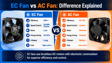
An EC fan is a fan driven by an Electronically Commutated motor, which is essentially a brushless DC (BLDC) motor with built-in electronics that convert AC line power to DC and handle the commutation internally. The result is a motor that achieves the high efficiency of a DC motor while running directly off standard AC mains supply.
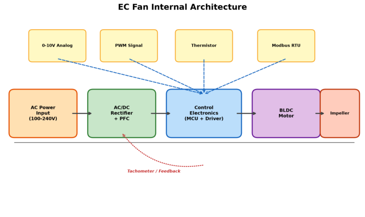
The integrated electronics do more than just convert power. They also provide a control interface that lets you adjust the fan speed anywhere from roughly 20% to 100% of its rated maximum, steplessly and without the efficiency penalties that plague AC motors at reduced speeds [8]. This built-in controllability is what makes EC fans so versatile, but it also means you need to pick the right control method for your specific application.

Figure 1. Internal architecture of an EC fan showing AC/DC conversion, control electronics, and multiple signal input options.
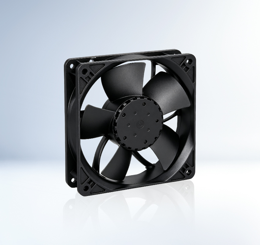
Leading manufacturers such as ebm-papst [1], Sanyo Denki [4], and Ziehl-Abegg [7] have spent decades refining EC motor technology. Their products typically accept multiple control input formats on a single fan, which gives system designers flexibility in how they interface with building automation or standalone controllers.
3. Why Speed Control Matters: The Affinity Laws
Before diving into specific control methods, it is worth understanding why speed control matters so much. The answer comes down to a set of fluid dynamics principles known as the fan affinity laws. These laws describe how fan performance changes with rotational speed.
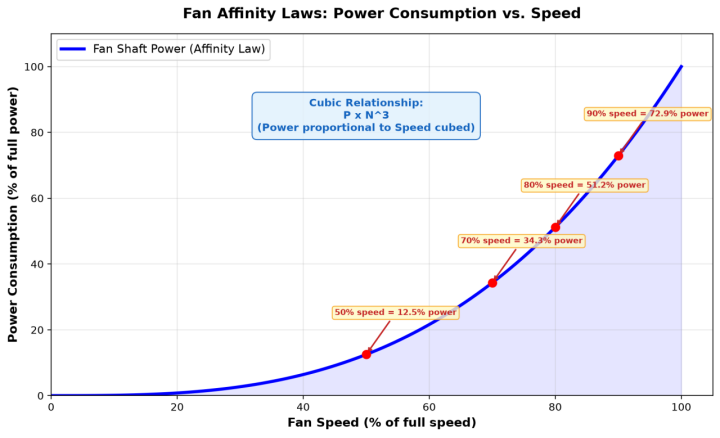
The key relationship is that power consumption is proportional to the cube of the fan speed. In practical terms, this means that reducing fan speed by just 20% cuts power consumption by nearly 50%. A 50% speed reduction drops power consumption to only 12.5% of full-load power. This cubic relationship is why variable-speed EC fans can deliver dramatic energy savings compared to fixed-speed AC fans that are always running flat out.

Figure 2. The cubic relationship between fan speed and power consumption demonstrates why even modest speed reductions yield large energy savings.
Beyond energy savings, speed control also reduces noise, extends bearing life (bearings last roughly twice as long at 20% reduced speed), and minimizes mechanical wear. Research published in Springer's Discover Applied Sciences confirms that a 10% fan speed reduction in mining ventilation saved approximately 30.59 kW, while a 20% reduction nearly doubled bearing life [5].
4. Method 1: 0-10V Analog Control
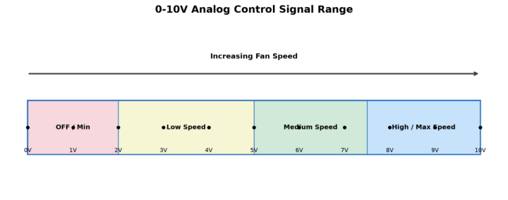
The 0-10V analog signal is the most common control method for EC fans in HVAC applications. It uses a simple DC voltage ranging from 0 to 10 volts to represent the desired fan speed. At 0V, the fan runs at its minimum speed (or stops entirely, depending on configuration). At 10V, the fan runs at full rated speed. Values in between produce proportional speed adjustment.

Figure 3. The 0-10V analog control signal maps voltage levels to fan speed ranges from off to maximum output.
The 0-10V signal does not power the fan motor. The fan still connects to its rated AC supply. A separate pair of low-voltage wires carries the control signal to the fan's integrated electronics. This separation keeps the control wiring safe and straightforward to install.
Advantages
Universal compatibility: Widely supported by virtually all EC fan manufacturers and HVAC controllers.
Simple wiring: Only two wires needed for the signal, and wiring mistakes rarely cause damage.
Easy integration: Any 0-10V output device, from thermostats to PLCs, can drive the fan.
Limitations
Signal degradation: Long cable runs can pick up electromagnetic interference, causing speed drift.
No bidirectional communication: The fan can report its running status back only through a separate tachometer wire, not via the control signal itself.
Limited precision: Resolution is limited by the analog-to-digital conversion in the fan electronics.
5. Method 2: PWM (Pulse Width Modulation) Control
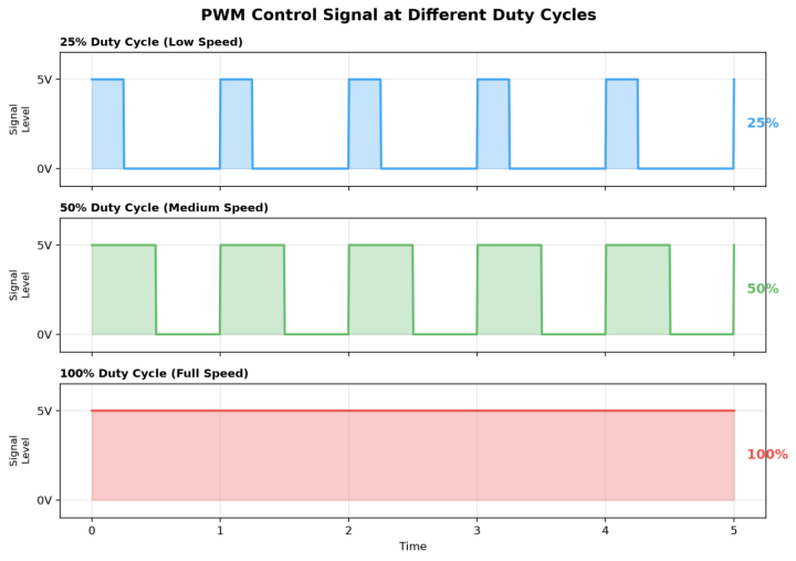
PWM control sends a digital square-wave signal to the fan, where the duty cycle, the percentage of time the signal is high versus low, determines the target speed. A 100% duty cycle commands full speed, 50% commands approximately half speed, and 25% commands roughly quarter speed. The fan continues to receive its rated supply voltage, while a separate control wire carries the PWM signal.

Figure 4. PWM signals at 25%, 50%, and 100% duty cycles, corresponding to low, medium, and full fan speeds.
PWM is a digital signal, which means it is inherently more resistant to noise than an analog voltage. The most common PWM frequency for EC fans is 25 kHz, though some manufacturers use 1 kHz. The 25 kHz standard keeps the signal above the audible range, preventing any electrical noise from being heard as a whine or buzz.
Advantages.
Noise immunity: Digital signals resist electromagnetic interference far better than analog voltages.
High precision: Duty cycle resolution can be very fine, often 1% steps or better.
Efficient wiring: A single wire can carry both the speed command and receive a tachometer feedback signal.
Limitations
Frequency matching: Some controllers output PWM at non-standard frequencies, requiring a signal converter.
Cable length limits: Signal integrity can degrade over very long cable runs without proper shielding.
6. Method 3: Thermistor-Based Temperature Control
For applications where the fan should respond automatically to temperature changes without an external controller, thermistor-based control is an elegant solution. A Negative Temperature Coefficient (NTC) thermistor is connected directly to the fan's control input. As the ambient temperature rises, the thermistor's resistance drops, and the fan electronics interpret this change as a command to increase speed.
Most EC fans that support thermistor control come with a predefined temperature-to-speed curve. For example, the fan might stay at minimum speed below 25 degrees C, ramp up linearly between 30 and 45 degrees C, and reach full speed above 50 degrees C. Some models allow you to program a custom curve using the manufacturer's configuration software.
Advantages
Zero controller cost: No external controller, PLC, or BMS required. The fan manages itself.
Fast response: The thermistor reacts to temperature changes within seconds.
High reliability: The thermistor is a passive component with no moving parts or electronics to fail.
Limitations
No remote override: You cannot override the speed manually or remotely without adding another control method.
Limited flexibility: The temperature-speed curve is fixed unless reprogrammed with manufacturer tools.
Placement sensitivity: Thermistor placement is critical. If it is not positioned where heat actually accumulates, the fan will not respond correctly.
7. Method 4: Potentiometer (Manual) Control
Sometimes the simplest approach is the best. Connecting a potentiometer, a variable resistor, to the fan's control input allows a person to manually dial the speed up or down by turning a knob. This method is common in applications where the fan serves a single space and an occupant or technician wants direct, tactile control over airflow.
The potentiometer effectively creates a variable voltage divider that the fan electronics read as a speed command. A 10 kOhm potentiometer is the most common value, though some fans accept other ranges. The knob can be surface-mounted on an enclosure, wall-mounted in a room, or installed on a control panel.
Advantages
Lowest cost: A potentiometer costs only a few dollars and requires no power supply.
Intuitive operation: Anyone can turn a knob. No training or software needed.
Universal fit: Works on any EC fan that accepts analog resistance input, with no compatibility issues.
Limitations
Manual only: Speed cannot be changed from a remote location or automated system.
Single-fan scope: Not suitable for large multi-fan systems where coordinated control is needed.
Wear and tear: The potentiometer has mechanical contacts that can wear out or get dirty over time.
8. Method 5: Modbus RTU / RS-485 Digital Communication
Modbus RTU over RS-485 is the workhorse of industrial digital communication, and many EC fan manufacturers support it as a control option. Instead of sending a simple voltage or pulse signal, Modbus sends structured digital messages that can command a specific speed, read back the actual RPM, monitor motor current, check fault status, and even adjust internal parameters like the minimum speed threshold.
RS-485 is a differential serial bus that can span up to 1,200 meters and connect up to 32 devices on a single twisted-pair cable. This makes it ideal for large installations with many fans spread across a building. Each fan gets a unique Modbus address, and the master controller polls each one in turn or broadcasts commands to all fans simultaneously.
Advantages
Full telemetry: Read fan speed, current, temperature, fault codes, and runtime hours.
Multi-drop bus: One twisted-pair cable can control dozens of fans, dramatically reducing wiring cost.
Precise command: Set precise RPM targets rather than approximate voltage-to-speed mappings.
Industry standard: Most industrial PLCs, SCADA systems, and BMS platforms speak Modbus natively.
Limitations
Setup complexity: The master controller must be configured with the correct register maps and baud rates for each fan model.
Single point of failure: Modbus is a single-master protocol. If the master goes down, all fans lose their control commands.
Vendor variation: Different fan manufacturers use different Modbus register addresses, creating interoperability headaches.
9. Method 6: BACnet and BMS Integration
BACnet is the dominant communication protocol in building automation. When EC fans support BACnet MS/TP (over RS-485) or BACnet/IP (over Ethernet), they can join a building management system as native objects. The BMS can then coordinate fan speeds with other HVAC equipment, such as dampers, chillers, and variable air volume boxes, to optimize overall system performance.
Some modern EC fans also support IoT protocols like MQTT or REST APIs, allowing cloud-based monitoring and control. This is particularly relevant for data center operators who want to track cooling performance across multiple sites from a single dashboard. The fan essentially becomes a networked device that reports its status and accepts commands through the same IT infrastructure as the rest of the facility.
While BACnet and BMS integration offer the highest level of control sophistication, they also carry the highest implementation cost and complexity. System integrators must be involved in commissioning, and the network infrastructure must be properly designed to handle the traffic from potentially hundreds of connected fans.
10. Comparison of Control Methods

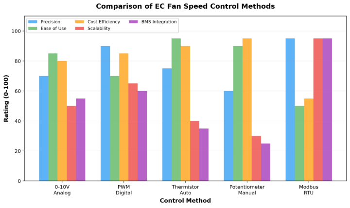
Figure 5. Side-by-side comparison of EC fan control methods across key performance dimensions [3].
|
Method |
Signal Type |
Wiring |
Best For |
Cost |
|
0-10V Analog |
Analog voltage |
2-wire + power |
General HVAC |
Low |
|
PWM Digital |
Digital pulse |
1-wire + power |
Electronics cooling |
Low |
|
Thermistor |
Resistance |
2-wire + power |
Stand-alone auto control |
Very low |
|
Potentiometer |
Variable resistance |
2-wire + power |
Manual single-fan |
Very low |
|
Modbus RTU |
Digital serial |
2-wire bus + power |
Multi-fan industrial |
Medium |
|
BACnet / BMS |
Digital network |
Network + power |
Smart buildings |
High |
11. Best Practices for Selecting a Control Method
Choosing the right speed control method is not about picking the most advanced option. It is about matching the control capability to the application requirements, budget, and maintenance resources. Here are some practical guidelines based on real-world engineering experience.
Single fan, simple need: If you are controlling one or two fans in a room and nobody needs remote access, a potentiometer is hard to beat. It is cheap, reliable, and requires no configuration.
Small to medium HVAC: For a few fans tied to a room thermostat or humidistat, 0-10V analog control is the industry standard. It works with virtually every thermostat and controller on the market.
Temperature-reactive cooling: If the fan should speed up when it gets hot and slow down when it cools off, with no human intervention, thermistor control eliminates the need for a separate controller entirely.
Large multi-fan systems: When you have 10 or more fans spread across a facility and need centralized control, Modbus RTU is the sweet spot between cost and capability. One cable run can reach all the fans.
Smart building integration: For new construction or major retrofits where the BMS is already part of the design, specify BACnet-capable EC fans from the start. Retrofitting BACnet later is expensive and often messy.
Always plan for failure: If a single controller failure would take down all cooling, design in redundancy. Use two Modbus masters in a hot-standby arrangement, or ensure fans default to a safe speed if they lose their control signal.
12. Common Applications
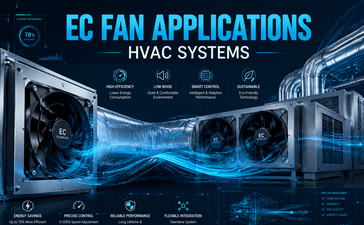
EC fans with speed control show up across a wide range of industries. Here are some of the most common scenarios [6]:
Air handling units (AHUs): EC fans in AHUs adjust speed based on duct static pressure sensors, maintaining consistent airflow while minimizing energy use. 0-10V or Modbus control is typical.
Data center cooling: Server racks use EC fans with PWM or thermistor control to ramp up cooling as server load increases, preventing hot spots without wasting energy during idle periods [2].
Refrigeration: EC fans in refrigerated display cases and cold storage facilities use thermistor or 0-10V control to match compressor load and maintain stable temperatures.
Agricultural ventilation: Grow facilities use Modbus-controlled EC fans integrated with climate controllers that manage temperature, humidity, and CO2 levels simultaneously.
Residential ventilation: EC fans in residential HRV/ERV systems run at low speed continuously and boost to high speed when humidity or CO2 sensors trigger, typically via 0-10V control.
13. Frequently Asked Questions (FAQ)
Q1: Can I use multiple control methods on the same EC fan simultaneously?
In most cases, no. EC fans typically accept one active control signal at a time. However, many fans have a priority hierarchy. For example, if both a 0-10V signal and a PWM signal are connected, the fan may default to whichever signal is present and ignore the other. Some advanced models support signal combining, where the fan responds to whichever command requests the higher speed. Always check the manufacturer's datasheet for the specific priority behavior.
Q2: What happens to an EC fan if the control signal is disconnected?
Most EC fans are designed to fail-safe. If the control signal wire is cut or disconnected, the fan will typically ramp up to full speed or a predefined default speed. This ensures that cooling is not lost in the event of a wiring fault. Some fans can be configured to stop instead, but this is less common and should only be used in applications where uncontrolled airflow is more dangerous than no airflow.
Q3: How much energy can I actually save by switching from AC fans to EC fans with speed control?
The savings depend on your duty cycle and how much time the fan spends at reduced speed. In a typical HVAC application where demand varies throughout the day, real-world energy savings of 30% to 50% are common when replacing fixed-speed AC fans with EC fans running on demand-based control. In data center cooling, where fans can run at 40-60% speed for extended periods, savings can exceed 70% thanks to the cubic affinity law relationship.
Q4: Do I need a variable frequency drive (VFD) to control EC fan speed?
No. This is one of the key advantages of EC fans over AC fans. The speed control electronics are built into the fan itself. You do not need an external VFD, which simplifies installation, reduces cost, and eliminates the EMI and motor heating issues that VFDs can introduce. All you need is the appropriate control signal, whether that is a 0-10V voltage, a PWM pulse train, or a Modbus data stream.
Q5: What is the minimum speed an EC fan can reliably run at?
Most EC fans can operate reliably down to approximately 20% to 30% of their rated maximum speed. Below this threshold, the motor may struggle to maintain stable rotation, and airflow can become turbulent and unpredictable. The exact minimum speed varies by fan model and manufacturer. Some fans allow you to program a minimum speed floor via Modbus or configuration software to prevent the control system from commanding a speed below the stable operating range.
14. References
[1] ebm-papst Group. Centrifugal fans with EC technology, product overview and technical specifications. https://www.ebmpapst.com.cn/en/products/centrifugal-fans.html
[2] ebm-papst Group. Server cooling solutions with EC technology, energy efficiency and control options. https://www.ebmpapst.com.cn/en/industries/air-conditioning/server-cooling.html
[3] AMCA International. Fan efficiency grades and system effects, AMCA Standard 205. https://amca.org/
[4] Sanyo Denki. PWM controller for speed control fans, technical datasheet (9PC series). https://products.sanyodenki.com/en/sanace/
[5] Siddiqui, M.A. et al. (2025). Maximizing energy savings in coal mines industrial ventilation: strategies and analysis for power reduction. Discover Applied Sciences, Springer. https://link.springer.com/article/10.1007/s42452-025-06989-0
[6] ASHRAE. ASHRAE Handbook: HVAC Applications, chapter on industrial ventilation and fan control. https://www.ashrae.org/technical-resources/ashrae-handbook
[7] Ziehl-Abegg. ECblue technology, fan speed control interfaces and application notes. https://www.ziehl-abegg.com/en/
[8] IEEE. Neethu, U. and Jisha, V.R. (2012), Speed Control of Brushless DC Motor: A Comparative Study. IEEE International Conference on Power Electronics, Drives and Energy Systems. https://ieeexplore.ieee.org/document/6464491